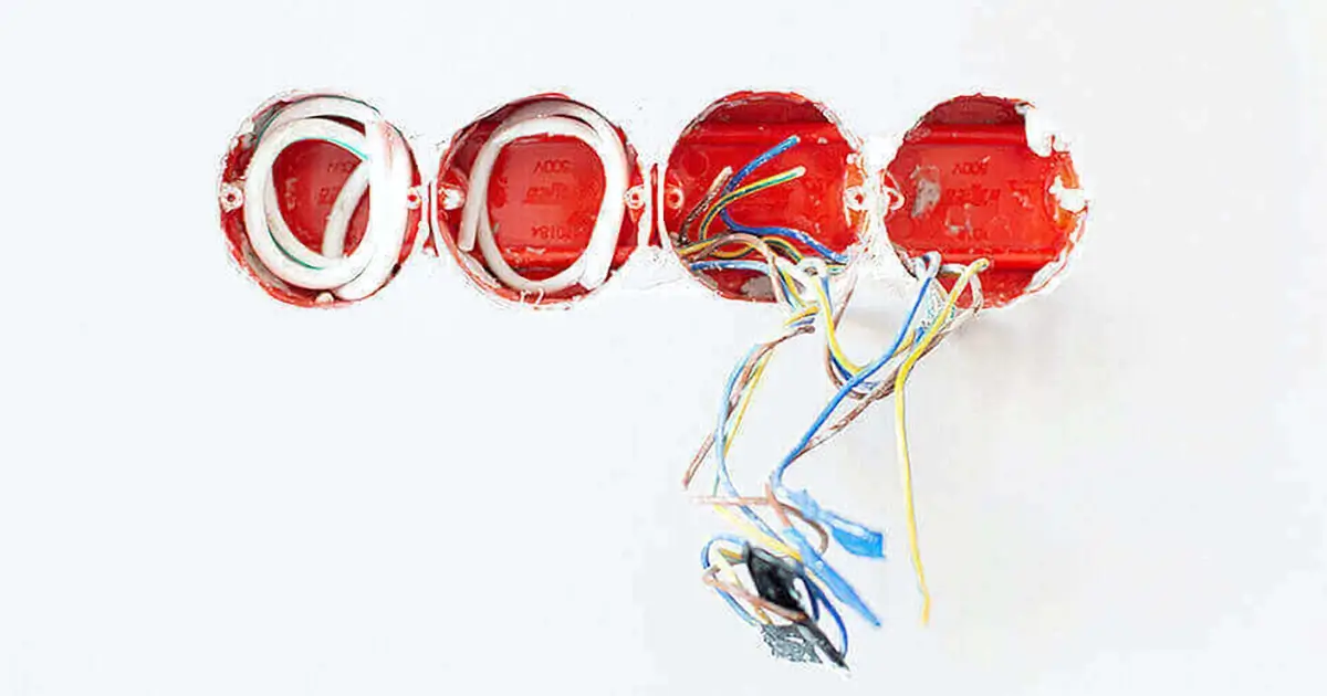
Many users have asked eBee Technology how to wire the WiFi thermostat. As a thermostat manufacturer, we made a wiring guide.
For the installation method of the entire WiFi thermostat, we have made a guide. Here we serve as a supplement. According to different HVAC systems, the following wiring methods are available.
- Wiring Method of WiFi Thermostat for Water Heating System
- Wiring Method of WiFi Thermostat for Boiler Heating System
- Wiring Method of WiFi Thermostat for Electric Heating System
- Wiring Method of WiFi Thermostat for Central Air Conditioning System
- Wiring Method of WiFi Thermostat for Air Source Heat Pump System
Then, show you our detailed diagram and wiring introduction.
Wiring Method of WiFi Thermostat for Water Heating System
For water heating thermostats, usually, the thermostat outputs a 5A electrical signal to control the execution of the valve switch, and the valve controls the flow of hot water in the water distribution system to transfer heat to each room.
Solenoid valves commonly have normally open valves and normally closed valves. Therefore, when the water heating thermostat is connected to the signal output line, the user needs to pay attention to the type of valve.
The thermostat manufactured by eBee Technology is powered by an external household power supply and has a live wire input and a neutral wire output.
In addition, some users will connect a temperature sensor outside the thermostat in order to obtain a more accurate temperature value. Therefore, eBee Technology reserves the NTC sensor ports on the thermostat.
Wiring Diagram of Water Heating Thermostat
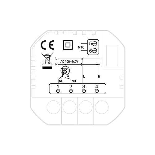
- Pin 1: Connect to the normally close valve (NC)
- Pin 2: Connect to the normally open valve (NO)
- Pin 3: Connect to Live Wire (L)
- Pin 4: Connect to Negative Wire (N)
- Pin 5 & 6: Connect to the external sensor (NTC)
Wiring Method of WiFi Thermostat for Boiler Heating System
For the boiler thermostat, is directly connected to the wall-hung boiler and uses dry contacts to control the on and off of the wall-hung boiler. When the indoor temperature is lower than the set value of the thermostat, the thermostat controls the wall-hung boiler to turn on and start heating water. The water circulates in the indoor waterway, driving the temperature of the whole room to rise. When the temperature reaches or exceeds the set value of the temperature, the thermostat controls the boiler to turn off.
Therefore, the wiring terminals of the boiler thermostat include dry contacts, power supply, and NTC sensors.
Wiring Diagram of Boiler Thermostat
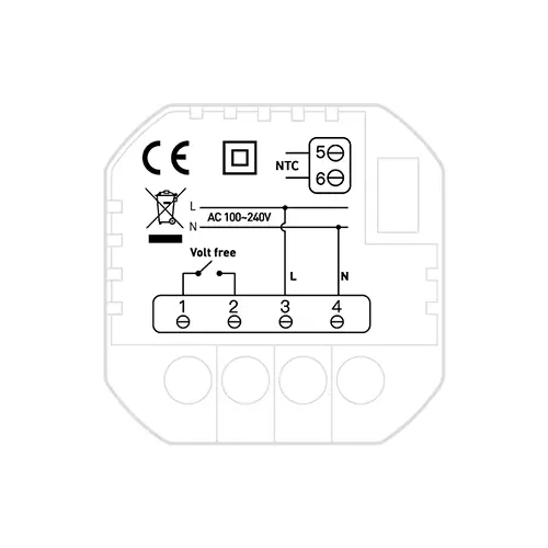
- Pin 1 & 2: Connect to the boiler heater(Volt free)
- Pin 3: Connect to Live Wire (L)
- Pin 4: Connect to Negative Wire (N)
- Pin 5 & 6: Connect to the external sensor (NTC)
Wiring Method of WiFi Thermostat for Electric Heating System
For the electric heating thermostat, it directly outputs a current of 16A to the heating cable or electric heating film. When the temperature sensor detects that the heating temperature reaches the set value, it stops the current output to realize the functions of heating and temperature control. In Europe, electric heating is the most common home heating method.
eBee Technology’s electric heating thermostat includes two neutral and live wire power supply terminals, two voltage output terminals (connecting heating cables, electric heating film), and two external sensor terminals.
Wiring Diagram of Electric Heating Thermostat
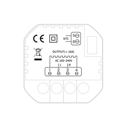
- Pin 1 & 4: Connect to the heating device (Load)
- Pin 2: Connect to Live Wire (L)
- Pin 3: Connect to Negative Wire (N)
- Pin 5 & 6: Connect to the external sensor (NTC)
Wiring Method of WiFi Thermostat for Central Air Conditioning System
For the central air conditioning thermostat, EBEE Technology’s thermostats are adapted to fan-coil unit type central air-conditioning. After the air-conditioning host generates cold or hot air, it is distributed in the building’s HVAC pipes and delivered to each room through the fan coil. The opening or closing of the valve on the fan coil unit determines whether the hot and cold air can be delivered. At the same time, the fan on the fan coil unit can be adjusted in different grades, usually 3 gears, and the comfort brought by the magnitude of the wind is also different. In principle, the control function of the air-conditioning thermostat is to adjust the switch of the cold valve and the hot valve of the fan coil, and the grades of the fan.
According to the classification of fan coil units, fan coil units are divided into two-pipe fan coil units, four-pipe fan coil units, and other types. The most commonly used in the market is two-pipe unit> four-pipe unit> other types. eBee Technology’s thermostats are suitable for two-pipe fan coil units and four-pipe fan coil units.
In connection processing, first of all, a 220V power supply port is a must, of course, users in some areas will use a safe voltage of 24V. Three levels of terminals are reserved for the fan, corresponding to the high, medium, and low levels of wind power, and two terminals for the cooling valve and heating valve. Similarly, we have reserved terminals for external sensors.
Wiring Diagram of Central Air Conditioning Thermostat
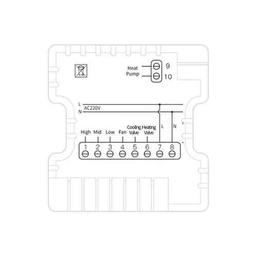
- Pin 1: High Speed
- Pin 2: Medium Speed
- Pin 3: Low Speed
- Pin 4: Fan
- Pin 5: Cooling Valve
- Pin 6: Heating Valve
- Pin 7: Connect to Live Wire(L)
- Pin 8: Connect to Negative Wire(N)
Wiring Method of WiFi Thermostat for Air Source Heat Pump System
For the air source heat pump thermostat, it is similar to the central air conditioner in that it is controlled by a fan and heating and cooling valves. However, the air source system realizes the dual supply of cooling and heating in winter and summer by converting high and low heat, which is more energy-efficient. At present, it is widely used in North America. With the promotion of energy-saving and environmental protection, more and more countries and regions are also promoting air-source heat pump systems.
Similarly, the wiring of the air source heat pump thermostat is divided into three levels, the air conditioning part, the floor heating part of the plumbing system, as well as the power supply.
Wiring Diagram of Air Source Heat Pump Thermostat
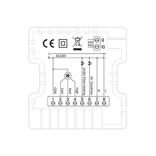
- Pin 1: COM
- Pin 2: Low Speed
- Pin 3: Medium Speed
- Pin 4: High Speed
- Pin 5: Underfloor Heating Valve
- Pin 6: Air Conditioning Valve
- Pin 7: Connect to Negative Wire (N)
- Pin 8: Connect to Live Wire (L)
- Pin 9 & 10: Dry Contact
The above is eBee Technology’s guide on thermostat wiring, we hope it can help you.