How to Add a Buzzer to Your Heltec T114 Node
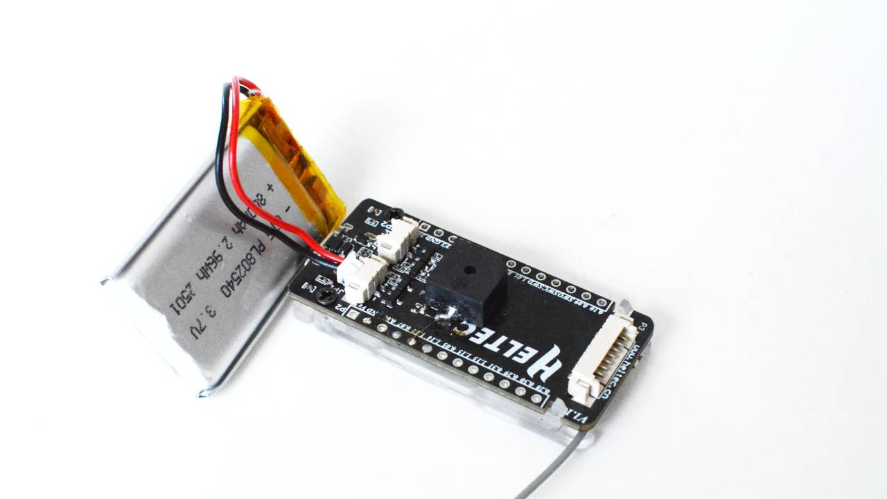
Enhancing your Heltec T114 node with a buzzer is a simple yet effective way to add audible alerts for notifications, alarms, or message alerts. This guide will walk you through the necessary steps to integrate a buzzer into your setup, ensuring seamless functionality.
Required Components
Before starting, gather the following components:
| Component | Quantity | Purchase Link |
|---|---|---|
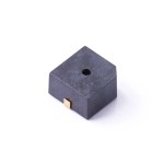
| Active Buzzer | 1 | EBEE Store |
Buzzer and jumper wires for Heltec T114 node
Step-by-Step Wiring Guide
-
Identify GPIO Pins
- The Heltec T114 node has multiple GPIO pins, but we recommend using GPIO 44 for the buzzer which is the nearest GPIO to the buzzer that can be soldered on board.
- The negative PIN of the buzzer can be soldered on the board directly.
-
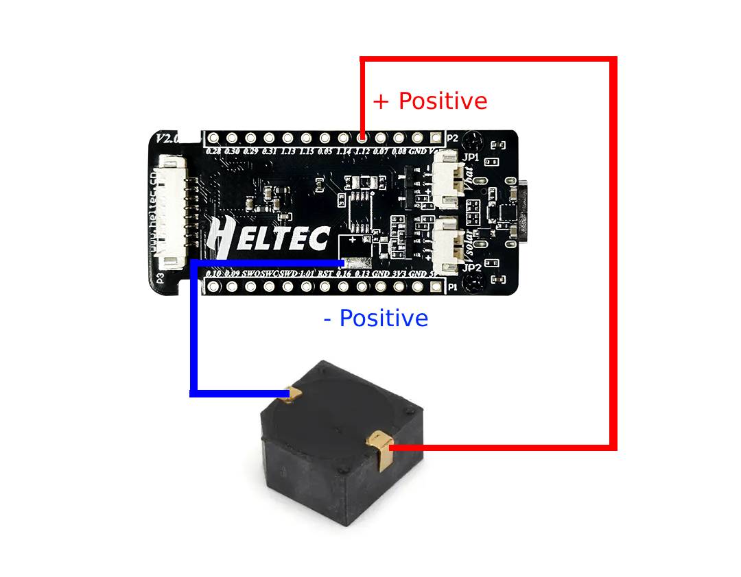
Connect the Buzzer
- Positive → P1.12 = GPIO 44
- Negative → GND
- Secure Connections
- Double-check all connections to avoid loose wiring.
- Use a breadboard or soldering for a permanent setup.
Configuring Meshtastic Settings
Once the hardware is set up, configure the Meshtastic software:
- Open the Meshtastic App (Android/iOS).
- Navigate to Settings > Module Configuration > External Notification.
- Enable the following options:
- Enable External Notification
- Alert When Receiving a Message
- Use PWM Buzzer
- Set the Output GPIO Pin to 44.
Testing the Buzzer
After configuration:
- Send a test message to your node.
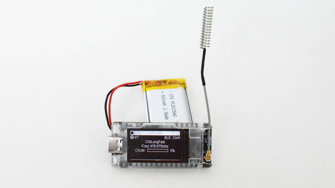
- The buzzer should emit a beep sound upon receiving the message.
If the buzzer doesn’t work:
- Verify wiring connections.
- Check if the GPIO pin is correctly assigned in the settings.
Need High-Quality Components?
For reliable buzzers, jumper wires, and other electronic components, contact EBEE at [email protected] for product inquiries and bulk orders.
eBee

We are the professional distributor of electronic components, providing a large variety of products to save you a lot of time, effort, and cost with our efficient self-customized service. careful order preparation fast delivery service